Opto-electronic components
Optoelectronic components (or as often referred to
photo-electronic components), are electronic components which produce
light or react to it. Some components among them are LEDs (Light Emitting
Diodes), photo transistors, photo diodes, photo resistors (or LDR – Light
Dependant Resistors), different visual indicators, light emitters and
detectors, optocouplers, etc. Many of those components can be recognized
easily recognized because of the “window” on the component's case which is
used to pass the light. Sometimes, instead of a window, there is a small
lens, which directs light to some predestined location inside of the
component. Some of the most important optoelectronic components are shown
on photo 9.1.
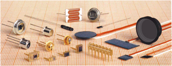
1. Photo-electronic components
We already mentioned the most frequently used component
of them – the LED. Basic role of a LED in circuits is a visual indicator
of, for example, state of the device (on/off), but is not rare in other
indicator appliances, voltage stabilizers, etc. There is an abundance of
colors, shapes and sizes to choose from, but most frequent ones are red,
green and yellow. Because of the different and more complicated
manufacturing process, blue ones cost a bit more than other ones. There
are square, housed, SMD, angled, ultra bright, multicolored and many other
kinds, but they all have the same principles of use.
 Another application of LEDs is a LED display. One
display is on 9.2. It is, as shown, facilitated out of 8 diodes marked
with an a,b,c,d,e,f,g and DP (DP being the Decimal Point). These devices
come in two possible flavors – with a common cathode (as this display), or
with a common anode. In both cases it is necessary to connect protection
resistors to to all diodes (which is the same as when working with
ordinary LEDs). Another application of LEDs is a LED display. One
display is on 9.2. It is, as shown, facilitated out of 8 diodes marked
with an a,b,c,d,e,f,g and DP (DP being the Decimal Point). These devices
come in two possible flavors – with a common cathode (as this display), or
with a common anode. In both cases it is necessary to connect protection
resistors to to all diodes (which is the same as when working with
ordinary LEDs).
Photo diodes are similar to other, ordinary, diodes
internally. One main difference is in that that photo diode has an exposed
surface to for light to fall onto. These diodes are acting as high value
resistor while in dark. It's resistance lowers as light gains in
intensity. In their behavior they are similar to photo resistors, apart
from that as with all diodes polarity of the component must be
appropriately positioned.
Emitting diodes are special kind of photo-diodes. One of
them is the LED, and some of them include infra-red or ultra-violet
emitting for different wireless communication purposes. Most common area
of application of IR-LEDs (Infra Red) are remote controllers for TVs and
other devices.
Photo diodes are usually housed in round metallic or
square plastic cases with a glass window or a lens which focuses the
incoming light.
Photo-transistor's internal parts are similar to
internals of a regular transistor. One main difference between them is the
glass window which allows light to reach the crystal plate which holds all
transistor's parts. With changes of light intensity, resistance between
base and the collector varies, and this influences variations of the
collector current. In this component light has the same role as voltage
over base of the regular transistor. When intensity rises, current through
the transistor rises as well, and other way round, if intensity fades,
current fades.
Photo electronic components are manufactured in an array
of different case shapes and sizes. Several of them, together with their
schematics symbols are displayed on 9.3.
One special group of
photo-electronic components are the optocouplers. These are special
integrated circuits facilitated out of an IR photo diode, and some
component which is sensitive to light (photo transistor, photo thyristor).
Diode is called an emitter, and “receiving” end is called the detector.
This means that the only connection between the emitter and detector is
through a ray of light. This is an important property of optocouplers,
since it allows two different parts of the circuit which operate on
different supply voltages to connect to each other without actually
conducting electricity, which means that one part could operate on 9V and
other on 5V without fear of burning the sensitive lower voltage
components.
There are several optocouplers and their cases on
9.4.
Photo transistors on 9.4a are connected to other components in the
same manner as ordinary transistors. Control of current which passes
through it is done by light falling onto it.
Voltage to the diode on
9.4a can be variable in time, but anode must always be positive compared
to the cathode. In case this component is used in an alternating current
circuit, diode emits light only during one half of the interval in which
anode is positive comparing to cathode. It is possible to use circuit on
9.4b in case it is needed for diode to be lit during both periods. This
circuit demonstrates two diodes in anti-parallel connection, so one of the
two is lit during each half of the period.
Picture 9.4c is an
optocoupler using a thyristor. Thyristor is connected to other components
in usual manner, and it starts conducting only upon receiving light
impulse created by the diode.
Transistor on 9.4d is controlled by
regulating either the light intensity of the diode or voltage over pin 6.
Same goes when using a triac on 9.4e, light intensity of the diode or
voltage on pin6 trigger the circuit.
Dual input NAND gate circuit is
used as a detector on the 9.4f, one of those inputs controls the voltage
on pin 7, and the other is controlling diode's light intensity. Logic zero
on pin 6 remains only in case pin 7 has a logic one and diode is lit, any
other case pin 6 has logic one.
2.
Examples
We offer a schematic of a device which detects a certain
level of intensity of ambient light, and when that level is detected, it
turns on a device connected to mains grid. Data on 9.5 shows that in
absence of light resistance of the LDR resistor, NORP12, is R=1MOhm, which
makes both base voltage and base current very low, so there is practically
no current flowing through transistor. Since there is no current flowing
through the coil of the relay it's other end is in switched off position.
When light intensity reaches certain point, resistance of the LDR lowers
(at around 10lx resistance is approximately 9kOhm), voltages and current
of the base rise, this current flows further through the relay's coil
which connects pins 1 and 3 and this switches on the wanted appliance to
the mains.
 Slider of the 5kOhm trimmer resistor sets sensitivity
of entire circuit. Lower the slider's position to lower the light level
that triggers the appliance on. Greatest sensitivity is reached when
trimmer is omitted from the circuit. Slider of the 5kOhm trimmer resistor sets sensitivity
of entire circuit. Lower the slider's position to lower the light level
that triggers the appliance on. Greatest sensitivity is reached when
trimmer is omitted from the circuit.
There is a possibility to use a
photo-diode instead of a LDR (cathode goes up, to + of the battery), or a
photo-transistor (collector up).
The device would be turned off when
light is absent in case we placed 47kOhm regular resistor instead, and LDR
between points A and B.
Each relay has a coil which accords to voltage
of the battery. In our case that is 12V.Resistance of the coil is several
hundreds of Ohms, and it shouldn't be lower than 120Ohm. Current rate
through the relay should be equal to or greater than needed by the device
plugged to mains. If, for example, we were looking at an 1kW electric
heater, it's current is equal to:
I=P/U=1000W/220V=4,5 A.
Any TUN transistor whose maximum current rating is higher
than current through relay's rate, is alright. This value is calculated by
dividing battery voltage with relay's coil resistance.
When we want to
employ remote control over some device, it is possible to utilize
different technologies, but in some cases cable connection or radio wave
control aren't the most appropriate ones, like the one between the TV and
it's remote controller. Some IR emitting and receiving photo diodes are
used specifically in low range transmitters and receivers. Block scheme on
9.6 represents usage of photo diodes between the sound source (hi-fi,
radio receiver, TV) and headphones, which removes the need for long
cables.
 Low frequency signal which is to be carried is
marked with uLF. Based on that frequency, IR transmitter modulates the HF
voltage, called the carrier. This modulated HF voltage is further sent to
emitting diode LD271. Variable light emitted by this diode varies
resistance of the receiving diode, and thus the HF signal created using
this variations is equal to the modulated signal on the transceivers end.
IR receiver is demodulating this signal, which transforms the received HF
signal into the original LF signal which is equal to the original sound.
This signal is further amplified and brought to headphones. Low frequency signal which is to be carried is
marked with uLF. Based on that frequency, IR transmitter modulates the HF
voltage, called the carrier. This modulated HF voltage is further sent to
emitting diode LD271. Variable light emitted by this diode varies
resistance of the receiving diode, and thus the HF signal created using
this variations is equal to the modulated signal on the transceivers end.
IR receiver is demodulating this signal, which transforms the received HF
signal into the original LF signal which is equal to the original sound.
This signal is further amplified and brought to headphones.
Using
optical components enables safe interfacing of different devices to your
home PC. There is a schematic on 9.7 which displays a simple way to
interface a random device to the parallel (printer) port of the computer.
For simplicity we chose to connect small portable radio receiver supplied
using a 9V battery.
Receiver, battery and the interface circuit are
connected to the parallel port using the male SUB-D 25 connector. Program
which is to control the circuit is easily developed in any programming
language. We display a sample program written in Q-Basic, it will turn the
receiver in 7am and turn it off in 7:30 am.
REM Wake up program
10 DO
20 LOOP
UNTIL TIME$="07:00:00"
30 OUT &H378, 128
40 SLEEP 900
50 OUT
&H378, 0
60 STOP
At 7 o'clock, voltage on pin 9 will turn to +5V, and it
will remain that way for the next 900seconds.
A bit more modern operating systems than Windows 95 will
have different ways of controlling the parallel port, and there is an
extensive knowledge base on the Internet for programming this kind of
operation on any operating system. Google is your friend!
Schematic of
another interface circuit on 9.8 enables connection of any device plugged
to the mains grid to be turned on or off. Control over this device is done
in the same fashion as done in previous program.
When, according to the
program pin 9 is +5V (logic one), diode will conduct electricity. Light
emitted by it switches the triac inside of the optocoupler on. This
current flows through the 150Ohm resistor and creates a voltage drop which
ignites the triac, which enables current flow from the mains, which powers
the device.
Maximum allowed current of the BT136 triac is 4A, which
means that maximum allowed power of the device is 990W. It is worth saying
that optocouplers should be used only with resistance load devices (light
bulbs, heaters...). When connecting inductance load devices like electro
motors, transformers and such, it is advised to use the relay
interfaces.
|