Microphones, speakers and headphones
Microphones, speakers and headphones are components
commonly used as the electro-acoustic transformers.Theory of operation of
microphones is that they convert sound waves into electric signals, which
are, at some later point, transformed back into sound through speakers or
headphones. Schematic symbols for these components are on 8.1.

1. Microphones
There are several different types of microphones in
existence today: carbon, dynamic, crystal, capacitative (electret
microphones), etc. Dynamic microphones are in most widespreaded usage, it
is nearly impossible to even consider not having them when recording music
or speech, and other in some other occasions when high fidelity is
demanded. Basically dynamic microphone is exactly the same as dynamic
speaker, with only difference being it's size. (In reality, when sound
quality is not the first priority, like small portable transceivers
(walkie-talkies), interphones and such, it isn't rare that instead of a
microphone you find a miniature dynamic speaker.)
Internal structure and the cross-section of a dynamic
microphone are represented on 8.2. Paper cylinder, to 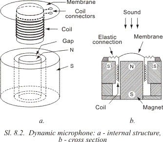 which a
copper wire is wound, is connected to a membrane which oscillates under
the force of variable sound pressure created by the sound source. This
coil is placed in a narrow gap with residing high magnetic field created
by a permanent magnet. Wire breaks out of the magnetic field, which,
according to Farad's law, induces variable voltage. This voltage is an
electric “image” of the sound which affects the membrane. which a
copper wire is wound, is connected to a membrane which oscillates under
the force of variable sound pressure created by the sound source. This
coil is placed in a narrow gap with residing high magnetic field created
by a permanent magnet. Wire breaks out of the magnetic field, which,
according to Farad's law, induces variable voltage. This voltage is an
electric “image” of the sound which affects the membrane.
Because of their low resistance, dynamic microphones
usually need separate transformer so they could be connected to some kind
of amplifier. This transformer is usually built-in the microphone's case.
If this transformer is absent from the circuit, it is necessary to connect
a preamplifier with low input resistance instead.
Carbon microphones were mainly used in telephony
applications, but they are being pushed back from there by some, more
advanced, modern microphones.
In past couple of years, electret microphones gained in
the number of applications in which they are being used, mostly in
portable and mass production devices. Electret microphone is a modern
variant of an old capacitative microphone. Some of it's main advantages
are it's small form factor, resistance to physical impacts, quality and
it's low price.
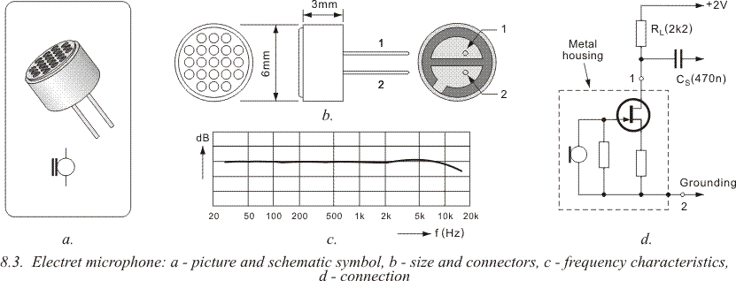
Shape, size and other characteristics of an electret
microphone are displayed on 8.3. Pay attention to it's miniature size,
equal to a thicker shirt button, and it's wide frequency range. Metal case
which houses this microphone has a single FET amplifier, which means that
this microphone needs DC voltage for supply. Bottom side has two pins
marked with 1 and 2. According to 8.3d, pin 2 is connected to the common
ground of the device (amplifier, etc.). Pin 1 is so called a “live pin”.
FET's resistor is connected between it and the positive battery end. FET
is used to amplify the low-frequency signal from the microphone. This,
amplified signal, is further connected over the capacitor CS.
2.
Speakers
Speakers, as well as microphones and headphones are
various in their shape and function. There are dynamic, crystal,
capacitative, but, as with microphones, most frequently used ones are the
dynamic speakers.
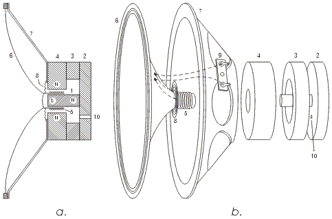 Cross section of an electrodynamic speaker is
displayed on 8.4a, and it's internal parts are on 8.4b. Ferrite encasing
rings (2, 3 and 4) are added to a large permanent magnet (1) which creates
strong magnetic field in the narrow gap between magnet's S and N poles.
Cylindrical bearing is added to the gap, and it holds a wound coil (5).
Coil endings are soldered to the small bolts on the inside of the
membrane, from where they are connected over elastic copper conductors to
the connectors (9) on the speaker case (7). Coil bearing is glued to the
paper membrane (6) on whose edge are several pressed channels used to
connect it to the case. Elastic connection, called a “butterfly
connection” (8), exists between the inner side of the membrane and the
speaker's case. This is necessary so that coil and it's bearing would
remain in the exact center of the empty gap, and coil wouldn't touch poles
of the magnet. With larger speakers, these elastic connections between the
membrane and the case are facilitated using thin, elastic rubber rings,
which enable long shifts of the membrane, and this elongated “walk” means
that it is possoble to draw more power from the speakers, wile keeping the
distortions inside of some normal expected limits. Cross section of an electrodynamic speaker is
displayed on 8.4a, and it's internal parts are on 8.4b. Ferrite encasing
rings (2, 3 and 4) are added to a large permanent magnet (1) which creates
strong magnetic field in the narrow gap between magnet's S and N poles.
Cylindrical bearing is added to the gap, and it holds a wound coil (5).
Coil endings are soldered to the small bolts on the inside of the
membrane, from where they are connected over elastic copper conductors to
the connectors (9) on the speaker case (7). Coil bearing is glued to the
paper membrane (6) on whose edge are several pressed channels used to
connect it to the case. Elastic connection, called a “butterfly
connection” (8), exists between the inner side of the membrane and the
speaker's case. This is necessary so that coil and it's bearing would
remain in the exact center of the empty gap, and coil wouldn't touch poles
of the magnet. With larger speakers, these elastic connections between the
membrane and the case are facilitated using thin, elastic rubber rings,
which enable long shifts of the membrane, and this elongated “walk” means
that it is possoble to draw more power from the speakers, wile keeping the
distortions inside of some normal expected limits.
Two most important characteristics of a speaker are it's
resistance and it's power. Resistances that are most commonly found in
appliances are 4, 8 and 16 Ohm, but there are also ones with 3,25,40 and
80 Ohm. Speaker powers range from only a fraction of Watt to several tens
of Watts, even hundreds of Watts.
Both this characteristics should be taken into
consideration while using or repairing audio equipment. If schematic
states that 8 Ohm speaker should be used, that is the resistance that
should be used, because when using for example lower value, there is a
possibility that the amplifier or the speaker may become permanently
damaged (which one of the two would be rendered useless depends on which
of the two has lower power). Speaker and amplifier would remain
functioning if this happened to be a higher resistance speaker than
supposed, but the output power would be considerably lower. Situation is a
bit different when considering speaker power. If maximum power is, for
example, 1W, then speaker's power shouldn't be lower than that (if this is
for some reason an unavoidable situation, level regulator should not be
turned to the max, because output power then exceeds 1W, which could prove
devastating for the speaker). Any speaker above 1W will work with our
example. This makes distortions lower and sound reproduction gains in
quality.
It is advisable to choose larger speakers and avoid
miniature ones whenever possible. This is so because larger speakers tend
to be more efficient (they are significantly louder) and sound
reproduction is of much higher quality, especially within the lower
frequencies range.
Speaker should be housed in a large, massive case because
the speaker box functions as a resonance box, and this greatly adds to the
overall quality of the sound reproduction. As you can see, when dealing
with speakers, size does make a difference.
For smaller appliances (alarm clocks and other alarm and
indication circuits) it is good enough to use miniature speakers in
plastic cases of the same shape as the housing of the electret microphone
on the 8.3a. Similar speaker is used in the alarm device on 7.8
“Buzzers” are miniature ceramic speakers, which could
also be used in these devices. They have very high resistance which makes
them easily compatible with digital ICs, since they could be connected
directly to them. For example, on 7.8 buzzer would have been connected
between pin 11 and ground.
3.
Headphones
Same goes for headphones as with microphones and
speakers. There are several types: dynamic, crystal and electromagnetic,
but dynamic ones are most commonly found nowadays. They are functioning on
the same principles, with same internal parts as dynamic speakers, with
obvious difference in construction, since they are intended for much lower
powers than speakers. Their main characteristic is their resistance, which
comes in range from several Ohms (dynamic), to several hundreds of
kiloohms (crystal headphones). Among amateurs, electromagnetic speakers
are a bit more popular, since they come in range from several hundreds of
ohms to several kiloohms, which enables them to be directly plugged into
various simple transistor amplifiers.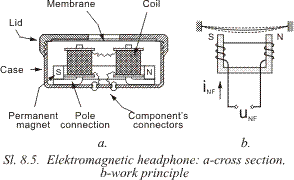
Cross
section of an electromagnetic headphone is displayed on 8.5a. Its
consisted of a permanent horseshoe shaped magnet with pole connectors that
hold two coils. Coils are in serial connection, which adds the magnetic
fields together. Membrane is shaped out of thin elastic steel plate. When
current doesn't flow through coils, permanent magnet holds stretched steel
membrane (8.5b). When there is a low frequency voltage over connections of
the headphones, LF current flows through the coils. This current creates
it's magnetic field, when it is aligned in direction with the permanent
magnet's field, membrane is shifted towards the magnet, when these
directions are opposite force lowers and membrane is shifted away from the
magnet. End positions of the membrane are depicted in dotted lines.
4.
Examples
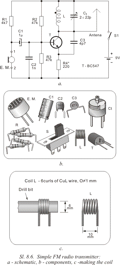 Schematic of one very simple radio-transmitter is on
8.6. It uses an electret microphone. It is a FM transmitter which emits on
a free frequency in range between 88MHz and 108MHz, so it's broadcasting
is possible to be received on an ordinary FM receiver. Schematic of one very simple radio-transmitter is on
8.6. It uses an electret microphone. It is a FM transmitter which emits on
a free frequency in range between 88MHz and 108MHz, so it's broadcasting
is possible to be received on an ordinary FM receiver.
Transistor,
along with a coil L, trimmer capacitor Ct, capacitor C3 and resistors R2,
R3 and R4 facilitates an oscillator which creates HF voltage whose
frequency is approximately:

In this equation CCB is representing a capacitance of the
collector circuit, or simpler, capacitance between the collector and the
base. Value of this capacitance depends on the voltage over the base:
higher the voltage, lower the capacitance and vice versa - lower voltage,
higher capacitance. Voltage over base is constant while there is no sound,
which means that the frequency of the oscillator is constant as well. When
sound appears, point 1 receives amplified LF voltage from the microphone.
It is, over C1, forwarded to the base of the transistor, and because of
that overall voltage over base changes (it actually oscillates around the
middle value determined by R2 and R3). With same frequency variates the
capacitance of the CCB, and thus the overall frequency of whole oscillator
variates as well. In this way is facilitated the frequency modulation
(FM).
Transceiver's frequency is determined in this way, by setting the
trimmer capacitor Ct, so frequency wouldn't overlap with some other radio
transceiver's frequency.
Antenna is devised of a grounded copper wire
whose whole length should be around 60cm.
Self-bearing coil L with
inner radius 6mm has 6 “curls” of 1mm copper wire. It is, as shown, wound
curl to curl over 6mm drill bit. Afterwards it is stretched so it's length
is around 10mm. Change of it's inductance is facilitated by squeezing or
stretching the coil (it is a negative proportion equation – longer the
stretch, lower the inductance, and vice versa).
Transmitter's range
depends on the used receiver and it's precision, but is around 70m. This
could be risen to some point by lowering the value of the resistor R4, or
shortened if higher value was used.
Stereophonic High Fidelity (or
Hi-Fi) sound reproduction is the main area of appliance of speakers. This
is true no matter if the speakers are connected to special
audio-amplifiers or amplifiers inside of radio and TV receivers, cassette
players, CD players, etc. In these products speakers are housed in special
speaker boxes or inside of the appliance's case. This is because frequency
range of sounds that are reproduced is between 30Hz and 15kHz. There is no
speaker in the world that could cover that whole range, and because of
that, speaker boxes often house two ore even more speakers with each
dedicated to it's own reproduction range. Speakers couldn't be simply
connected in parallel, to do this right there is a special junction
circuit whose sole purpose is to “send” the signal to whichever speaker
dedicated for that frequency.
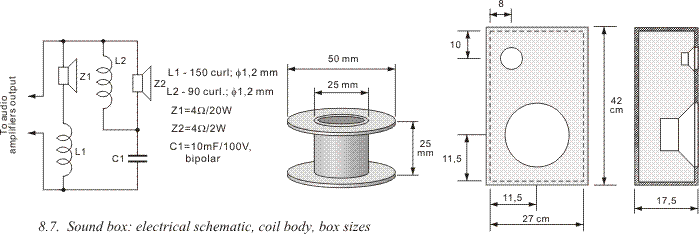
Double speaker box is our example is
represented on 8.7: Z1 reproduces sounds from 30 Hz to 800 Hz and Z2
reproduces sounds with frequencies from 800 Hz to 15 kHz. Coils L1 and L2
and capacitor C1 are components facilitating electronic junctions.
 Headphones are most commonly used with portable
devices, like small radio receivers, cassette and cd walkmans, mp3
players, etc. They could be used in stationary devices as well, because
they enable listening music very loud without disturbing the public peace
and causing neighbor unrest. Aside from that, headphones maintain very
high quality of reproduction for only a fraction of price for sound boxes
of the same quality. All modern devices have an audio-amplifier. It is
usually devised using an integrated circuit, and most of these circuits
are designed for 32W of power. And this is why most of today's headphones
have that power rating as well, although there 16W headphones could be
found as well. Headphones are most commonly used with portable
devices, like small radio receivers, cassette and cd walkmans, mp3
players, etc. They could be used in stationary devices as well, because
they enable listening music very loud without disturbing the public peace
and causing neighbor unrest. Aside from that, headphones maintain very
high quality of reproduction for only a fraction of price for sound boxes
of the same quality. All modern devices have an audio-amplifier. It is
usually devised using an integrated circuit, and most of these circuits
are designed for 32W of power. And this is why most of today's headphones
have that power rating as well, although there 16W headphones could be
found as well.
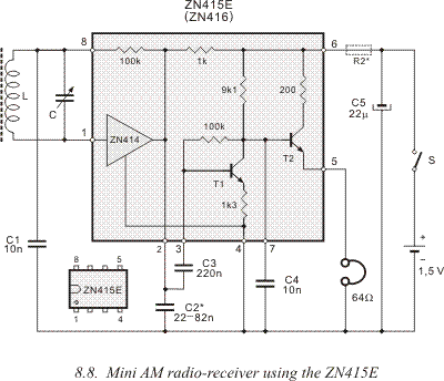
Schematic of a portable radio receiver for medium
frequency range is on 8.8. It's built around the ZN416 integrated circuit.
Reproduction is over two serially connected 32W headphones, with overall
power rating being 64W.
It is possible to join two examples, and to
connect the radio receiver on 8.8 and the schematic on 7.3, which enables
this receiver for speaker reproduction.
|

