Resistors
Resistors are
the most commonly used component in electronics and their purpose is to
create specified values of current and voltage in a circuit. A
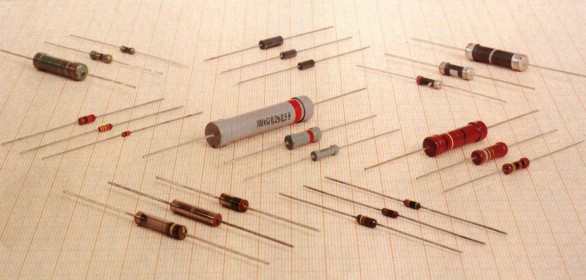
number of different resistors are shown in the photos. (The resistors are
on millimeter paper, with 1cm spacing to give some
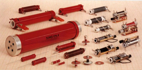
idea of the dimensions). Photo 1.1a shows some low-power resistors, while photo 1.1b shows some
higher-power resistors. Resistors with power dissipation below 5 watt (most
commonly used types) are cylindrical in shape, with a wire protruding from
each end for connecting to a circuit (photo 1.1-a). Resistors with power dissipation above 5 watt are
shown below (photo 1.1-b).
|
|
| Fig.
1.1a: Some low-power resistors |
Fig. 1.1b:
High-power resistors and
rheostats |
The symbol for a resistor is shown in
the following diagram (upper: American symbol, lower: European symbol.)

Fig. 1.2a: Resistor symbols
The unit for
measuring resistance is the OHM. (the Greek letter Ω). Higher resistance values are represented by "k"
(kilo-ohms) and M (meg ohms). For
example, 120 000 Ω
is represented as 120k, while 1 200 000 Ω is represented as 1M2. The dot
is generally omitted as it can easily be lost in the printing process. In some circuit
diagrams, a value such as 8 or 120 represents a resistance in ohms.
Another common practice is to use the letter E for resistance. For
example, 120E (120R) stands for 120 Ω, 1E2 stands for 1R2 etc.
1. Resistor Markings
Resistance value is
marked on the resistor body. The first three bands provide the value of
the resistor in ohms and the fourth band indicates the tolerance.
Tolerance values of 5%,
2%, and 1% are most commonly available.
The following table shows the colors used
to identify resistor values:
| COLOR |
DIGIT |
MULTIPLIER |
TOLERANCE |
TC |
| Silver |
|
x 0.01 W |
±10% |
|
| Gold |
|
x 0.1 W |
±5% |
|
| Black |
0 |
x 1 W |
|
|
| Brown |
1 |
x 10 W |
±1% |
±100*10-6/K |
| Red |
2 |
x 100 W |
±2% |
±50*10-6/K |
| Orange |
3 |
x 1 kW |
|
±15*10-6/K |
| Yellow |
4 |
x 10 kW |
|
±25*10-6/K |
| Green |
5 |
x 100 kW |
±0.5% |
|
| Blue |
6 |
x 1 MW |
±0.25% |
±10*10-6/K |
| Violet |
7 |
x 10 MW |
±0.1% |
±5*10-6/K |
| Grey |
8 |
x 100 MW |
|
|
| White |
9 |
x 1 GW |
|
±1*10-6/K |
** TC - Temp. Coefficient, only for
SMD devices
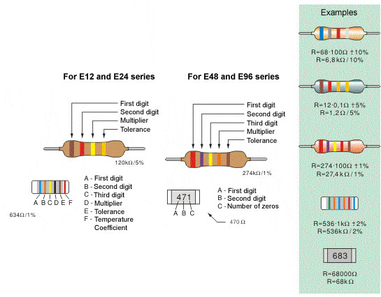
Fig. 1.2: b. Four-band resistor, c. Five-band resistor,
d. Cylindrical SMD resistor, e. Flat SMD resistor
The following shows all resistors from
1R to 22M:
NOTES:
The resistors above are "common value" 5%
types.
The fourth band is called the "tolerance" band. Gold = 5%
(tolerance band Silver =10% but no modern resistors are
10%!!)
"common resistors" have values 10 ohms to 22M.
RESISTORS LESS THAN 10 OHMS
When the third band
is gold, it indicates the value of the "colors" must be divided by
10.
Gold = "divide by 10" to get values 1R0
to 8R2
See 1st Column above for examples.
When the third band is silver, it indicates the value of the "colors" must be divided by
100.
(Remember: more letters in the word "silver" thus the divisor is
"larger.")
Silver = "divide by 100" to get
values R1 to R82
e.g: 0R1 = 0.1 ohm 0R22
= point 22 ohms
See 4th Column above for
examples.
The letters "R, k and M" take the place of a decimal
point.
e.g: 1R0 = 1 ohm 2R2 = 2
point 2 ohms 22R = 22 ohms
2k2 =
2,200 ohms 100k = 100,000
ohms
2M2 = 2,200,000 ohms
Common resistors have 4
bands. These are shown above. First
two bands indicate the first two digits of the resistance, third band is
the multiplier (number of zeros that are to be added to the number derived
from first two bands) and fourth represents the tolerance.
Marking the resistance with
five bands is used for resistors with tolerance of 2%, 1% and other
high-accuracy resistors. First three bands determine the first three
digits, fourth is the multiplier and fifth represents the tolerance.
For SMD (Surface Mounted
Device) the available space on the resistor is very small. 5% resistors
use a 3 digit code, while 1% resistors use a 4 digit code.
Some SMD resistors are made in
the shape of small cylinder while the most common type is flat.
Cylindrical SMD resistors are marked with six bands - the first five are
"read" as with common five-band resistors, while the sixth band determines
the Temperature Coefficient (TC), which gives us a value of resistance
change upon 1-degree temperature change.
The resistance of
flat SMD resistors is marked with digits printed on their upper side.
First two digits are the resistance value, while the third digit
represents the number of zeros. For example, the printed number 683 stands
for 68000W , that is 68k.
It is self-obvious that there is mass production of all
types of resistors. Most commonly used are the resistors of the E12
series, and have a tolerance value of 5%. Common values for the first two
digits are: 10, 12, 15, 18, 22, 27, 33, 39, 47, 56, 68 and 82.
The E24
series includes all the values above, as well as: 11, 13, 16, 20, 24, 30,
36, 43, 51, 62, 75 and 91. What do these numbers mean? It means that
resistors with values for digits "39" are: 0.39W, 3.9W, 39W, 390W, 3.9kW, 39kW, etc are manufactured.
(0R39, 3R9, 39R, 390R, 3k9, 39k)
For some electrical circuits,
the resistor tolerance is not important and it is not specified. In that
case, resistors with 5% tolerance can be used. However, devices which
require resistors to have a certain amount of accuracy, need a specified
tolerance.
2. Resistor Dissipation
If the flow of
current through a resistor increases, it heats up, and if the
temperature exceeds a certain critical value, it can be damaged. The
wattage rating of a resistor is the power it can dissipate over a long
period of time.
Wattage rating is not identified on small resistors.
The following diagrams show the size and wattage rating:
Fig. 1.3: Resistor dimensions
Most commonly used
resistors in electronic circuits have a wattage rating of 1/2W or 1/4W.
There are smaller resistors (1/8W and 1/16W) and higher (1W, 2W, 5W,
etc).
In place of a single resistor with specified dissipation,
another one with the same resistance and higher rating may be used, but
its larger dimensions increase the space taken on a printed circuit board
as well as the added cost.
Power (in watts) can be calculated according to one of
the following formulae:
where V represents resistor voltage in Volts, I is the current flowing
through the resistor in Amps and R is the resistance of resistor in
Ohms. For example, if the voltage across an 820W resistor is 12V, the wattage dissipated by the resistors
is:
A 1/4W resistor can
be used.
In many cases, it is
not easy to determine the current or voltage across a resistor. In this
case the wattage dissipated by the resistor is determined for the "worst"
case. We should assume the highest possible voltage across a resistor,
i.e. the full voltage of the power supply (battery, etc).
If we mark
this voltage as VB, the lowest dissipation
is:

For example, if VB=9V, the dissipation of a 220W resistor is:
A 0.5W or higher wattage resistor should
be used
3. Nonlinear resistors
Resistance values
detailed above are a constant and do not change if the voltage or
current-flow alters. But there are circuits that require resistors to
change value with a change in temperate or light. This function may not be
linear, hence the name NONLINEAR RESISTORS.
There are several
types of nonlinear resistors, but the most commonly used include : NTC resistors (figure a) (Negative Temperature Co-efficient) -
their resistance lowers with temperature rise. PTC resistors
(figure b) (Positive Temperature Co-efficient) - their resistance
increases with the temperature rise. LDR resistors (figure c)
(Light Dependent Resistors) - their resistance lowers with the increase in
light. VDR resistors (Voltage dependent Resistors) - their
resistance critically lowers as the voltage exceeds a certain value.
Symbols representing these resistors are shown below.
Fig. 1.4: Nonlinear resistors - a. NTC, b. PTC, c.
LDR
| In
amateur conditions where nonlinear resistor may not be available, it
can be replaced with other components. For example, NTC resistor may be replaced with a transistor with a trimmer
potentiometer, for adjusting the required resistance value.
Automobile light may play the role of PTC resistor,
while LDR resistor could be replaced with an open transistor.
As an example, figure on the right shows the 2N3055, with its upper
part removed, so that light may fall upon crystal plate. |
 |
4. Practical
examples with resistors
Figure 1.5 shows two practical
examples with nonlinear and regular resistors as trimmer potentiometers,
elements which will be covered in the following chapter.
Fig. 1.5a: RC amplifier
Figure 1.5a represents the so
called RC voltage amplifier, that can be used for amplifying
low-frequency, low-amplitude audio signals, such as microphone signal.
Signal to be amplified is brought between node 1 and gnd (amplifier
input), while the resulting amplified signal appears between node 2 and
gnd (amplifier output). To get the optimal performance (high
amplification, low distortion, low noise, etc) , it is necessary to "set"
the transistor's operating point. Details on operating point will be
provided in chapter 4; for now, let's just say that DC voltage between
node C and gnd should be approximately one half of battery (power supply)
voltage. Since battery voltage equals 6V, voltage in node C should be set
to 3V. Adjustments are made via resistor R1.
Connect the voltmeter between
node C and gnd. If voltage exceeds 3V, replace the resistor
R1=1.2MW with another, smaller resistor, say
R1=1MW. If voltage still exceeds 3V, keep
lowering the resistance until reaching approximately 3V. In case that
voltage in node C is originally lower than 3V, follow the same procedure,
but keep increasing the resistance of R1.
Amplified signal is gained on resistor R2
from figure 1.5a. Degree of amplification depends on R2 resistance: higher resistance - higher amplification, lower resistance -
lower amplification. Upon changing the resistance R2, voltage in node
C should be checked and adjusted if necessary (via R1).
Resistor R3 and 100µF capacitor
together form a filter to prevent feedback from occurring across positive
supply conductor, between the amplifier from figure 1.5a and the next
amplifier level. This feedback manifests itself as a high-pitched noise
from the speakers. In case of this occurring, resistance R3 should be
increased (to 820W, then to 1kW, etc)
until the noise stops.
Practical examples with regular resistors
will be plenty in the following chapters, since there is practically no
electrical scheme without resistors.
Fig. 1.5b: Sound indicator
of changes in temperature or the amount of light
Practical use for nonlinear resistors is
illustrated on a very simple alarm device, with electrical scheme shown on
figure 1.5b. Without trimmer TP and nonlinear NTC resistor it is an audio
oscillator. Frequency of the sound it generates can be calculated
according to the following formula:

In our case, R=47kW and
C=47nF, and the frequency equals:
When, according to the figure, trimmer pot
and NTC resistor are added, oscillator frequency increases but it keeps
"playing". If trimmer pot slider is set to the uppermost position,
oscillator stops working. At the desired temperature, slider should be
lowered very carefully until the oscillator starts working again. For
example, if these settings were made at 2°C, oscillator remains still at
higher temperatures than that, as NTC resistor's resistance is lower than
nominal. If temperature falls the resistance increases and at 2°C
oscillator is activated.
If NTC resistor is installed on the car,
close to the road surface, oscillator can warn driver if the road is
covered with ice. Naturally, resistor and two copper wires connecting it
to the circuit should be protected from dirt and water.
If, instead of NTC resistor, PTC resistor
is used, oscillator will be activated when temperature rises above certain
designated value. For example, PTC resistor could be used for indicating
the state of refrigerator: set the oscillator to work at temperatures
above 6°C via trimmer TP, and the loud sound will signal if anything's
wrong with the fridge.
Instead of NTC, we could use LDR resistor
- oscillator would be blocked as long as there is certain amount of light
present. In this way, we could make a simple alarm system for rooms where
light must be always on.
LDR can be coupled with resistor R. In
that case, oscillator works when the light is present, otherwise it is
blocked. This could be an interesting alarm clock for huntsmen and
fishermen who would like to get up in the crack of dawn, but only if the
weather is clear. In the desired moment in the early morning, pot slider
should be set to the uppermost position. Then, it should be carefully
lowered, until the oscillator is started - this the desired position of
the slider. During the night, oscillator will be blocked, since there is
no light and LDR resistance is very high. As amount of light increases in
the morning, LDR resistance drops and the oscillator is activated when LDR
is illuminated with the accurate amount of light matching the previous
settings.
Trimmer pot from the figure 1.5b is used
for fine adjustments. Aside from that, it can be used for modifying the
circuit, if needed. Thus, TP from figure 1.5b can be used for setting the
oscillator to activate under different conditions (higher or lower
temperature or amount of light).
5.
Potentiometers
Potentiometers (also called pots)
are variable resistors, used as voltage or current regulators in
electronic circuits. By means of construction, they can be divided into 2
groups: coated and coiled.
With coated potentiometers, (figure 1.6a),
insulator body is coated with a resistive material. There is an elastic,
conductive slider moving across the resistive layer, increasing the
resistance between slider and one end of pot, while decreasing the
resistance between slider and the other end of pot.
Fig. 1.6a: Coated potentiometer
Coiled potentiometers are made of
conductor wire coiled around insulator body. There is an elastic,
conductive slider moving across the wire, increasing the resistance
between slider and one end of pot, while decreasing the resistance between
slider and the other end of pot.
Coated pots are much more common variant.
With these, resistance can be linear, logarithmic, inverse-logarithmic or
other function depending upon the angle or position of the slider. Most
common are linear and logarithmic potentiometers, and the most common
applications are radio-receivers, audio amplifiers, and similar devices
where pots are used for adjusting the volume, tone, balance,
etc.
Coiled potentiometers are used in devices
which require increased accuracy and constancy of attributes. They feature
higher dissipation than coated pots, and are therefore a necessity in high
current circuits.
Potentiometer resistance is commonly of E6
series, most frequently used multipliers including 1, 2.2 and 4.7.
Standard tolerance values include 30%, 20%, 10% (and 5% for coiled
pots).
Potentiometers come in many different
shapes and sizes, with wattage ranging from 1/4W (coated pots for volume
control in amps, etc) to tens of Watts (for regulating high currents).
Several different pots
are shown in the photo 1.6b, along with the symbol for a
potentiometer.
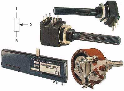
Fig. 1.6b: Potentiometers
Uppermost models represent the so called
stereo potentiometer. These are actually two pots in one casing, with
sliders mounted on shared axis, so they move simultaneously. These are
used in stereophonic amps for simultaneous regulation of both LF channels,
etc.
Lower left is the so called ruler
potentiometer, with a slider moving across straight line, not in circle as
with other pots.
Lower right is coiled pot with wattage of
20W, commonly used as rheostat (for regulating current while charging
accumulator and similar).
For circuits that demand very accurate
voltage and current value, trimmer potentiometers (or just trimmers) are used. These are small potentiometers with slider that
is adjusted via screw (unlike other pots where adjustments are made via
push-button mounted upon the axis which slider is connected
to).
Trimmer potentiometers also come in many
different shapes and sizes, with wattage ranging from 0.1W to 0.5W. Image
1.7 shows several different trimmers, along with the symbol for this element.
Fig. 1.7: Trimmer potentiometers
Resistance adjustments are
made via screw. Exception is the trimmer from the lower right corner,
which can be also adjusted via plastic axis. Particularly fine adjusting
can be achieved with the trimmer in plastic rectangular casing (lower
middle). Its slider is moved via special transmission system, so that
several full turns of the wheel are required to move slider from one end to the other.
6. Practical
examples with potentiometers
As previously stated,
potentiometers are most commonly used in amps, radio and TV receivers,
cassette players and similar devices. They are used for adjusting volume,
tone, balance, etc.
As an example, we will analyze
the common circuit for tone regulation in audio amps. It contains two pots
and is shown in the figure 1.8a.
Fig. 1.8 Tone regulation
circuit: a. Electrical scheme, b. Function of amplification
Potentiometer marked as BASS
regulates low frequency amplification. When its slider is in the lowest
position, amplification of very low frequency signals (tens of Hz) is
about ten times greater than the amplification of mid frequency signals
(~kHz). If slider is in the uppermost position, amplification of very low
frequency signals is about ten times lower than the amplification of mid
frequency signals. Low frequency boost is useful when listening to music
with a beat (disco, jazz, R&B...), while LF amplification should be
reduced when listening to speech or classical music.
In similar fashion,
potentiometer marked as SOPRANO regulates high frequency amplification.
High frequency boost is useful when music consists of high-pitched tones
such as chimes, while for example HF amplification should be reduced when
listening to an old record to reduce the noise.
Diagram 1.8b shows the function
of amplification depending upon the signal frequency. If both sliders are
in their uppermost position function is described with a curve 1-2, if
both are in mid position function is described with a line 3-4, and if
both sliders are in their lowest position function is described with a
curve 5-6. Setting the pair of sliders to any other possible position
results in a curve between curves 1-2 and 5-6.
Potentiometers BASS and SOPRANO
are coated by construction and linear by resistance function.
Third pot from the image serves
as volume regulator. It is also coated by construction, but is logarithmic
by resistance function (hence the mark log underneath
it)
Example with trimmer is given
in the text accompanying the image 1.5b.
|