Capacitors
Capacitors are
common components of electronic circuits, used almost as frequently as
resistors. Basic difference between the two is the fact that capacitor
resistance (called reactance) depends on voltage frequency, not only on
capacitors' features. Common mark for reactance is Xc and it
can be calculated using the following formula:
f representing the frequency in Hz and C representing the capacity in Farads.
For example, 5nF-capacitor's reactance at f=125kHz equals:
while, at f=1.25MHz, it equals:
Capacitor has
infinitely high reactance for direct current, because f=0.
Capacitors are used in circuits for
filtering signals of specified frequency. They are common components of
electrical filters, oscillator circuits, etc.
Basic characteristic of capacitor is its
capacity - higher the capacity is, higher is the amount of
electricity capacitor can accumulate. Capacity is measured in Farads (F).
As one Farad represents fairly high capacity value, microfarad (µF),
nanofarad (nF) and picofarad (pF) are commonly used. As a reminder,
relations between units are:
1F=106µF=109nF=1012pF,
that is 1µF=1000nF and
1nF=1000pF. It is essential to remember this notation, as same values may
be marked differently in different electrical schemes. For example, 1500pF
may be used interchangeably with 1.5nF, 100nF may replace 0.1µF, etc. Bear
in mind that simpler notation system is used, as with resistors. If the
mark by the capacitor in the scheme reads 120 (or 120E) capacity equals
120pF, 1n2 stands for 1.2nF, n22 stands for 0.22nF, while .1µ (or .1u)
stands for 0.1µF capacity and so forth.
Capacitors come in various shapes and sizes, depending on
their capacity, working voltage, insulator type, temperature coefficient
and other factors. All capacitors can divided in two groups: those with
changeable capacity values and those with fixed capacity values. These
will covered in the following chapters.
1. Block-capacitors
Capacitors with fixed capacity values (the so
called block-capacitors) consist of two thin metal bands, separated
by thin insulator foil. Most commonly used material for these bands is
aluminum, while the common materials used for insulator foil include
paper, ceramics, mica, etc after which the capacitors get named. A number
of different block-capacitors are shown in the photo below. A symbol for a
capacitor is in the upper right corner of the image.
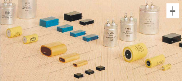
Fig. 2.1: Block capacitors
Most of the capacitors,
block-capacitors included, are nonpolarized components, meaning that both
of their connectors are equivalent in respect of solder. Electrolytic
capacitors represent the exception as their polarity is of importance,
which will be covered in the following chapters.
2. Marking the block-capacitors
Commonly, capacitors
are marked by a number representing the capacity value printed on the
capacitor. Beside this value, number representing the maximal capacitor
working voltage is mandatory, and sometimes tolerance, temperature
coefficient and some other values are printed too. If, for example,
capacitor mark in the scheme reads 5nF/40V, it means that capacitor with
5nF capacity value is used and that its maximal working voltage is 40v.
Any other 5nF capacitor with higher maximal working voltage can be used
instead, but they are as a rule larger and more expensive.
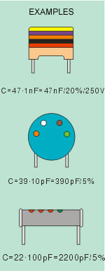
Sometimes, especially with capacitors of
low capacity values, capacity may be represented with colors, similar to
four-ring system used for resistors (figure 2.2). The first two colors (A
and B) represent the first two digits, third color (C) is the multiplier,
fourth color (D) is the tolerance, and the fifth color (E) is the working
voltage.
With
disk-ceramic capacitors (figure 2.2b) and tubular capacitors (figure 2.2c)
working voltage is not specified, because these are used in circuits with
low or no DC voltage. If tubular capacitor does have five color rings on
it, then the first color represents the temperature coefficient, while the
other four specify its capacity value in the previously described
way.
|
 |
| COLOR |
DIGIT |
MULTIPLIER |
TOLERANCE |
VOLTAGE |
| Black |
0 |
x 1 pF |
±20% |
|
| Brown |
1 |
x 10
pF |
±1% |
|
| Red |
2 |
x 100
pF |
±2% |
250V |
| Orange |
3 |
x 1 nF |
±2.5% |
|
| Yellow |
4 |
x 10
nF |
|
400V |
| Green |
5 |
x 100
nF |
±5% |
|
| Blue |
6 |
x 1 µF |
|
|
| Violet |
7 |
x 10 µF |
|
|
| Grey |
8 |
x 100 µF |
|
|
| White |
9 |
x 1000 µF |
±10% |
|
|
Fig. 2.2: Marking the capacity using colors
The figure 2.3 shows
how capacity of miniature tantalum electrolytic capacitors is marked by
colors. The first two colors represent the first two digits and have the
same values as with resistors. The third color represents the multiplier,
which the first two digits should be multiplied by, to get the capacity
value expressed in µF. The fourth color represents the maximal working
voltage value.
|
| COLOR |
DIGIT |
MULTIPLIER |
VOLTAGE |
| Black |
0 |
x 1 µF |
10V |
| Brown |
1 |
x 10 µF |
|
| Red |
2 |
x 100 µF |
|
| Orange |
3 |
|
|
| Yellow |
4 |
|
6.3V |
| Green |
5 |
|
16V |
| Blue |
6 |
|
20V |
| Violet |
7 |
|
|
| Grey |
8 |
x .01 µF |
25V |
| White |
9 |
x .1 µF |
3V |
| Pink |
|
|
35V |
|
Fig. 2.3: Marking the tantalum electrolytic capacitors
One important note
on the working voltage: capacitor voltage mustn't exceed the maximal
working voltage as capacitor may get destroyed. In case when the voltage
between nodes where the capacitor is about to be connected is unknown, the
"worst" case should be considered. There is the possibility that, due to
malfunction of some other component, voltage on capacitor equals the power
supply voltage. If, for example, the power supply is 12V battery, then the
maximal working voltage of used capacitors should exceed 12V, for
security's sake.
3. Electrolytic capacitors
Electrolytic
capacitors represent the special type of capacitors with fixed capacity
value. Thanks to the special construction, they can have exceptionally
high capacity, ranging from one to several thousand µF. They are most
frequently used in transformers for leveling the voltage, in various
filters, etc.
Electrolytic capacitors are polarized
components, meaning that they have positive and negative connector, which
is of outmost importance when connecting the capacitor into a
circuit. Positive connector has to be connected to the node with a high
voltage than the node for connecting the negative connector. If done
otherwise, electrolytic capacitor could be permanently damaged due to
electrolysis and eventually destroyed.
Explosion may also occur if capacitor is
connected to voltage that exceeds its working voltage. In order to prevent
such instances, one of the capacitor's connectors is very clearly marked
with a + or -, while working voltage is printed on capacitor
body.
Several
models of electrolytic capacitors, as well as their symbols, are shown on
the picture below.
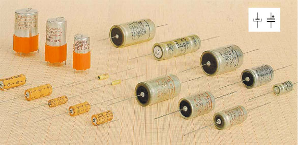
Fig. 2.4: Electrolytic capacitors
Tantalum capacitors
represent a special type of electrolytic capacitors. Their parasitic
inductance is much lower then with standard aluminum electrolytic
capacitors so that tantalum capacitor with significantly (even ten times)
lower capacity can completely substitute an aluminum electrolytic
capacitor.
4. Variable capacitors
Variable capacitors
are capacitors with variable capacity. Their minimal capacity ranges from
10 to 50pF, and their maximum capacity goes as high as few hundred pF
(500pF tops). Variable capacitors are manufactured in various shapes and
sizes, but common feature for all of them is a set of immobile,
interconnected aluminum plates called stator, and another set of plates,
connected to a common axis, called rotor. In axis rotating, rotor plates
get in between stator plates, thus increasing capacity of the device.
Naturally, these capacitors are constructed in such a way that rotor and
stator plates are placed consecutively. Insulator (dielectric) between the
plates is a thin layer of air, hence the name variable capacitor with air
dielectric. When setting these capacitors, special attention should be
paid not to band metal plates, in order to prevent short-circuiting of
rotor and stator and ruining the capacitor.
Bellow
is the photo of the variable capacitor with air dielectric
(2.5a).
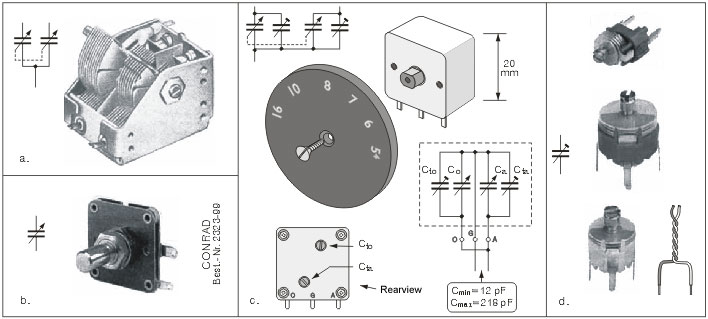
Fig. 2.5: a, b, c. Variable capacitors, d. Trimmer
capacitors
These are actually
two capacitors with air dielectric whose rotors share the common
axis, so that axis rotation changes the
capacities of both capacitors. These two-fold capacitors are used in radio
receivers: larger one is used in the input circuit, and the smaller one in the local
oscillator. Symbol for such capacitors is shown by the photo.
Contour line points to the
fact that the rotors are mechanically and electrically interconnected. If
one part of variable capacitor should be connected to the mass, which is
often the case, then it is rotor(s).
Beside the capacitors with air dielectric,
there are also variable capacitors with solid insulator. With these, thin
insulator foil occupies the space between stator and rotor, while
capacitor itself is contained in a plastic casing. These capacitors are
much more resistant to mechanical damage and quakes, which makes them very
convenient for portable electronic devices. One such one-fold capacitor is
shown on the figure 2.5b.
Variable capacitors are not readily
available in amateur conditions, but can be obtained from worn out radio
receivers, for example (these capacitors are usually Japanese in origin).
One such capacitor, used in portable radio receivers with AM area only, is
shown on the figure 2.5c. The plastic casing contains four capacitors, two
variacs and two trimmers, connected according to the scheme from the upper
left corner. Connecting the pins according to the lower scheme gets us a
one fold variable capacitor with capacity ranging from 12pF to
218pF.
The most
common devices containing variable capacitors are the radio receivers,
where these are used for frequency tuning. Semi-variable or trimmer
capacitors are miniature capacitors, with capacity ranging from several pF
to several tens of pFs. These are used for fine tuning in the radio
receivers, radio transmitters, oscillators, etc. Three trimmers, along
with their symbol, are shown on the figure 2.5d.
5. Practical examples with capacitors
Several practical examples with
capacitors are shown on the figure 2.6. The figure 2.6a shows a
5µF electrolytic capacitor
used for the signal filtering. It is used for getting the LF signal from
the previous block to the transistor basis, amplifying it and reproducing
via headphones. The capacitor prevents the DC from the previous block
getting to the transistor basis. This occurs because the capacitor of
sufficiently high capacity acts like a resistor of very low resistance for
LF signals, and as a resistor of infinitely high resistance value for DC.
Fig. 2.6: a. Amplifier with headphones, b. Electrical band-switch
The figure 2.6b
represents a scheme of electrical band-switch with two speakers, with Z1
used for reproducing low and mid-frequency tones, and Z2 used for high
frequency tones. Nodes 1 and 2 are connected to the audio amplifier
output. Coils L1 and L2 and the capacitor C ensure that low and
mid-frequency currents flow to the speaker Z1, while high frequency
currents flow to Z2. How this works exactly ? In case of high frequency
current, it can flow through either Z1 and L1 or Z2 and C. Since the
frequency is high, reactance (resistance) values of coils are high, while
the capacitor's reactance value is low. It is clear that in this case,
current will flow through Z2. In similar fashion, in case of low-frequency
impulses, currents will flow through Z1, due to high capacitor reactance
and low coil reactance.
Fig. 2.6: c. Detector radio-receiver
The figure 2.6c
represents an electrical scheme of simple detector radio-receiver, where
the variable capacitor C, forming the oscillatory circuit with the coil L,
is used for frequency tuning. Turning the capacitor's rotor changes the
resonating frequency of the circuit, and when matching a certain
radio-emitter's frequency, an appropriate radio program can be
heard.
|