Coils and transformers
1. Coils
Coils are not that
common components of electronic devices as resistors and capacitors are.
They are encountered in various oscillators, radio-receivers,
radio-emitters and similar devices containing oscillatory circuits. In
amateur conditions, coil can be made by coiling one or more layers of
isolated copper wire onto a cylindrical insulator body (PVC, cardboard,
etc.) in a specified fashion. Factory made coils come in different shapes
and sizes, but the common feature for all of them is an insulator body
with coiled copper wire.
Basic characteristic of every coil is its
inductance. Inductance is measured in Henry (H), but more common are
milihenry (mH) and microhenry (µH) as one
Henry is quite high inductance value. As a reminder:
1H = 1000mH = 106 µH.
Coil
reactance is marked by XL, and can be calculated using
the following formula:

where f represents the frequency of coil voltage in Hz and the L represents
the coil inductance in H.
For example,
if f equals 684 kHz, while L=0.6 mH, coil reactance will be:

The same coil would
have three times higher reactive resistance at three times higher
frequency and vice versa. As can be seen from the formula above, coil
reactance is in direct proportion to voltage frequency, so that coils, as
well as capacitors, are used in different circuits for filtering voltage
of specified frequency. Note that coil reactance equals zero for DC, for f=0 in that case.
Several coils are shown on the figures 3.1,
3.2, 3.3, and 3.4.
The simplest
form of coil is single-layer air core coil. It is made of cylindrical
insulator body (PVC, cardboard, etc.) wrapped in isolated copper wire in
specific pattern, as shown on the figure 3.1. On the figure 3.1a, curls
have a certain amount of space left between them, while the common
practice is to coil the wire with practically no space left between curls.
To prevent coil unfolding, wire ends should be put through little holes as
shown on the figure, but some sticky tape could also do the
job.
Fig. 3.1: Single-layer coil w/o core: a. Regular, b.
With an outconnector
The figure 3.1b shows how the
coil is made. For instance, if the coil totals 120 curls
with an outconnector on the thirtieth curl, then there are two coils L1
with 30 curls and L2 with 90 curls one next to the other (or one over the
other) on the same coil body. When the end of the first and the beginning
of the second coil are soldered, we get the outconnector.
Multilayered coil is shown on the figure 3.2a. The
inner side of the plastic coil body is fashioned as a screwhole, so that
the ferromagnetic coil core in shape of small screwbolt can fit in.
Screwing the core moves it along the coil axis, and nearing it to the
center of the coil increases the inductance. In this manner, fine
inductance settings can be made.
Fig. 3.2: a. Multi-layered coil w core, b. Coupled
coils
The figure 3.2b shows the
high-frequency transformer. As it can be seen, these are two coils coupled by magnetic induction on a shared body. In case
when the coils are required to have exact specified inductance values,
each coil has ferromagnetic core that can be moved along the coil
axis.
At very high
frequencies (above 50mHz) required coil inductance value is relatively
low, so these coils consist of merely few curls. These coils are made of
thick, copper wire (approx. 1mm) with no coil body, as shown on the figure
3.3a. Their inductance can be adjusted by physical stretching or
contracting.
Fig. 3.3: a. High frequency coil, b.
Inter-frequency transformer
The figure 3.3b
shows the metal casing containing two bonded coils, with an electrical
scheme on the right. The parallel connection of the first coil and the
capacitor C forms an oscillatory circuit. The second coil is used for
transferring the signal to the next block. This mechanism is used in
receivers and similar devices. Metal casing serves as faradic cage,
preventing the external magnetic influence and containing the internal
magnetic field produced by the coil currents. In order to be used as a
cage, metal casing has to be grounded.
Coil in the "pot" casing made of ferromagnetic material is
shown on the figure 3.4. These coils are used at lower frequencies
(10kHz). Fine inductance adjustments can be made using the screw made of
ferromagnetic material.
Fig. 3.4: Coil in the "pot" casing: a. outlook, b.
Symbol and a scheme
Another kind of coils are the
so called defusers featuring very high reactance at working frequency and
very low resistance for DC. There are HF defusers (used at
high frequencies) and LF defusers (used at low frequencies). HF
defusers look similar to the described coils. LF defusers are made with
the cores identical to those used with network transformers. Symbol for
HF defusers is the one used for the previously described
coils, while the symbol for LF defusers looks like the one used for coils
with core, with bold line or two thin lines instead of the broken
line.
2. Transformers
For electronic
devices to function it is necessary to provide the DC power supply.
Batteries and accumulators can fulfill the role, but much more efficient
way is to use the converter. The basic component of the converter is the
network transformer for transforming 220V to a certain lower value, say
12V. Network transformer has one primary coil which connects to the
network voltage (220V) and one or several secondary coils for getting
lower voltage values. Most commonly, cores are made of the so called E and
I transformer sheet metal, but cores made of ferromagnetic tape are also
used. There are also iron core transformers used at higher frequencies in
converters. Various models of transformers are shown on the picture
below.
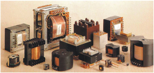
Fig. 3.5: Various models of transformers
Symbols of network
transformers are shown on the figure 3.6; 3.6a and 3.6b are more accurate
representations, while 3.6c and 3.6d are simpler to draw or
print. Two vertical lines indicate that primary and secondary coils
share the core made of transformer sheet metal.
Fig. 3.6: Transformer symbols
With the
transformer, manufacturers usually supply a scheme containing info on the
primary and secondary coil, voltage and maximal currents. In case that
this scheme is lacking, there is a simple method for determining which
coil is the primary and which is the secondary: as primary coil consists
of thinner wire and greater number of curls than the secondary, it has
higher resistance value - the fact that can be easily tested by ohmmeter.
The figure 3.6d shows the symbol for transformer with two independent
secondary coils, one of them having three outconnectors. The secondary
coil for getting 5V is made of thinner wire with maximal current 0.3A,
while the other coil is made of thicker wire with maximal current 1.5A.
Total voltage on the larger secondary coil is 48V, as shown on the
figure 3.6d. Note that voltage values other than those marked on the
scheme can be produced - for example, voltage between nodes marked as 27V
and 36V equals 9V, voltage between nodes marked as 27V and 42V equals 15V,
etc.
3. Working principles and basic characteristics of
transformers
As already stated,
transformers consist of two coils, primary and the secondary (figure 3.7).
When the voltage Up is brought to the primary coil (in our case it
is network voltage, 220V) the AC current Ip flows through it. This
current creates the alternate magnetic field which encompasses the
secondary coil, inducing the voltage Us (24V in our example).
Consumer is connected to the secondary coil - consumer is exemplified here
with the resistor Rp (30Ω in our example). Of course, it is never a
simple resistor but is some electronic device with an input resistance Rp. A simplest model would be an electric bulb working at 24V with
electric power 19.2W. Most commonly it is a guiding part of the converter,
consuming 0.8A current, etc.
Fig. 3.7: Transformer: a. Working principles, b.
Symbol
Transfer of electrical energy from the
primary to the secondary coil is carried out via magnetic field. To
prevent energy losses, it is necessary to assure that the whole magnetic
field created by the primary coil encompasses the secondary. This is
achieved by using the iron core, which has much lower magnetic resistance
value than the air, thus containing almost entire magnetic field within
the core.
Basic characteristics of transformers are
primary and secondary voltage, primary and secondary current (or power)
and the efficiency.
Primary voltage equals the network voltage.
This value can be 220V or 110V, depending on the standards of the country.
Secondary voltage is usually much lower, say 6V, 9V, 15V, 24V, etc, but
can also be higher than 220V, depending on the transformer's purpose.
Relation of the primary and the secondary voltage is given with the
following formula:

where Ns and Np represent the
number of curls of primary and secondary coil, respectively. For instance,
if Ns equals 80 and Np equals 743, secondary voltage will
be:
Relation between the primary and the secondary current is
described by the following formula:

For instance, if Rp equals 30Ω, than
the secondary current equals Ip = Up/Rp = 24V/30Ω =
0.8A. If Ns equals 80 and Np equals 743, primary current
will be:
Transformer power can be calculated by one
of the following formulae:
In our example, the power
equals:

Everything said up to this point relates to
the ideal transformer. Clearly, there is no such thing as losses are
inevitable. They are present due to the fact that the coil wire exhibits a
certain resistance value, which makes the transformer warm up during the
work, and the fact that the magnetic field created by the primary does not
entirely encompass the secondary coil. This is why the electrical power of
the secondary current has to be lower than the power of the primary
current. Their ratio is called efficiency:

For transformers with power measuring
hundreds of Watts, efficiency is about µ=0.85, meaning that 85% of the
electrical energy taken from the network gets to the consumer, while the
15% is lost due to previously mentioned factors in the form of heat. For
example, if electrical power of the consumer equals Up*Ip = 30W,
then the power which the transformer draws from the network
equals:
To avoid any
confusion here, bear in mind that manufacturers have already taken every
measure in minimizing the losses of transformers and other electronic
components and that, practically, this is the top possible efficiency for
the present. When acquiring a transformer, you should only take care of
the required voltage and the maximal current of the secondary coil. If the
salesman cannot tell you the exact value of the current, he should be able
to tell you the transformer's power. Dividing the values of power and the
secondary voltage gets you the maximal current value for the consumer.
Dividing the values of power and the primary voltage gets you the current
that the transformer draws from network, which is important to know when
buying the fuse. Anyhow, you should be able to calculate any value you
might need using the appropriate formulae from above.
4. Practical examples with coils and
transformers
On the figure
2.6b coils, along with the capacitor, form two filters for conducting the
currents to speakers. Coil and the capacitor C on the figure 2.6c form a
parallel oscillatory circuit for filtering high-frequency radio signals,
where the capacitor is used for tuning. Diode, 100pF capacitor and the
headphones form a detector for filtering and reproducing audio
signals.
Fig. 2.6: a. Amplifier with headphones, b. Electrical band-switch, c. Detector radio-receiver
The most obvious
application of transformers are converters, of course. One network
transformer is shown on the figure 3.8 and is used for converting 220V
voltage to 24V. Network voltage (220V) is brought to the primary coil
using the on/off converter switch and the fuse that protects the converter
from severe damage. It is very important that you bear in mind the fact
that network voltage (220V) is very dangerous and to be careful when
handling devices with network power supply. For practical realization of
converter, one from the figure 3.8 or any other, the original power
supply cable has to be used. There is no room for improvisation here,
so don't experiment with ordinary isolated wires and such.
Fig. 3.8: Stabilized converter with circuit
LM317
Input DC voltage can
be adjusted via linear potentiometer P, in 3~30V range.
Fig. 3.9: a. Stabilized converter with circuit 7806, b.
auto-transformer, c. transformer for devices
working at 110V, d. separating transformer
The figure 3.9a
shows a simple converter, using a network transformer with an outconnector
on the middle of the secondary coil. This makes possible to use two diodes
instead of the bridge from the
figure 3.8.
Special kind of
transformers, mainly used in
laboratories, are the auto-transformers. The scheme of an auto-transformer
is given on the figure 3.9b. It features only one coil, coiled on the iron
core used with regular transformers. Isolation is taken off from this
coil's exterior so that the sliding contact could be attached. When the
slider is in its lowest position, voltage equals zero. Moving the slider
upwards raises the voltage U, reaching 220V in the node A. Further moving
the slider increases the voltage U over 220V.
Transformer from the figure
3.9c with secondary voltage 110V is used for supplying the devices
supposed to work with network voltage 110V, as standards differ in various
countries. When using the converter for this purpose, bear in mind
that problems may occur if the network voltage frequency is 60Hz instead
of 50Hz.
As the final example, figure
3.9d represents a scheme of the so called detachment transformer. This
transformer features the same number of curls on primary and secondary
coils. Secondary voltage is same as the primary, 220V, but is completely
isolated from the public network, minimizing the risks of electrical
shock. As a result, person can stand on the wet floor, etc and to touch
and operate any part of the secondary coil without risks, which is not the
case with the power outlet.
|