Other components
There is an enormous amount of different electronic
components in use nowadays all around the world. This unfortunately means
that many of them will remain unexplained in this book, because such task
would quickly become impossible to achieve. But we will cover some of the
most important “other” components which you will come to meet in future
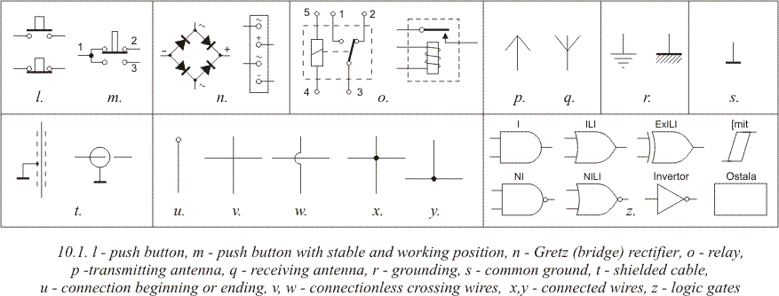
editions of “Practical ELECTRONICS”. Their symbols are on 10.1.

Fuses (10.1a) have single role in circuit - to apprehend
heavy failures and damages of the circuits. What this means is that some
high power devices, like different amplifiers, radio receivers, TVs, and
such, rise the amount of current flow from the mains during some
instabilities, which could result in serious damages of your appliance. To
prevent this from happening, fuses are installed inside of the device.
Fuse is usually made out of a glass tube holding a thin wire which burns
out on current flow anomalies and shuts down the whole device, and by
sacrificing itself, saves other, more expensive components. Most commonly
fuses could be found in the transformer part of the device. One of the two
metal caps has fuse's specifications printed on it: it's specified work
load, and burnout point.
Ordinary electric light bulb with a heating
thread is on 10.1b. It's resistance depends on the temperature it is
heated to. Usual light bulb's resistance when heated is ten to twenty
times higher than when it is cold.
VDR resistors' resistance (10.1d)
depends on the voltage brought to them: higher the voltage, higher the
resistance. They found their usage in different voltage protection
devices. If they, for example, receive voltage higher than 220V, their
resistance rises and this “soaks” the excess voltage.
Symbol for a DC
voltage battery is on 10.1e.
Quartz crystal oscillator is on 10.1f.
Quartz oscillator is a thin quartz plate pressed between two metal plates
and packed in a metal case connected to the plates. Quartz crystal
oscillator is commonly used as a stabilizer for some electronic oscillator
units, or as a clock source in microprocessor designs. Nowadays it's price
is very low, but in past it has been acquired by dismantling some old
electronic clock.
Instrument for measuring current (A) and voltage (V)
is on 10.1g. This symbol dates from times when analog equipment with
needle was in usage. Symbol remains the same nowadays, although digital
instruments have replaced analog ones long time ago.
AC voltage symbol
is on 10.1h. If there was more than one sine-wave, it is a high-frequency
(HF) AC voltage source. Square-wave and sawtooth instead of a sine-wave
represent square-wave or sawtooth voltage.
The simplest form of a
switch device is displayed on 10.1i. It's lever has two positions, one
when it is non-conductive, thus the controlled device is switched off and
conductive, when the device is on. Because of the wide usage of switches,
there are many different ones among them. For example, two pole switch
(10.1j) has two operating positions, in one position it connects points 1
and 2, and in the other it connects points 1 and 3.
There are switches
with even more operating positions, on 10.1k there is an example switch
with a rotation switch with four positions.

Momentary switches, or push buttons (10.1l) have a
built-in spring, which makes the switch conduct only while it is being
pressed (your standard doorbell has this kind of switch). There is an
opposite effect component, whose points are constantly connected, while
button pressing opens the circuit (these switches are commonly referred to
as reset buttons). Another possibility is a three-contact push button
(10.1m). When button is not pressed it connects points 1 and 2, and when
it is pressed it connects points 1 and 3.
Four diodes in a single case
(10.1n), connected in a Gretz (or often named bridge connection) are used
as two way directors in transformers. It's plastic case has four
connectors on it's sides: two marked with sine waves, used to connect the
AC voltage, and two marked with a + and a -, where comes an electrolithic
capacitor, which produces a DC voltage.
Relay symbols are represented
on 10.1o. When electromagnet receives sufficient voltage on points 4 and
5, connection between points 2 and 3 is opened, and at the same time
closed between points 3 and 1. Relay is actually an electromagnetic
switch. This means that you can design a circuit which automatically
toggles on and off based on some conditions which were predefined when the
circuit was designed.
Symbols for a receiver (10.1p) and transmitter
(10.1q) antenna.
Grounding symbols (10.1r). Grounding and common ground
aren't the same thing, but if both exist in a circuit, they are always
connected to each other. With electronic devices housed in a metal case,
grounding is connected to the metal housing. You will be able to spot a
ground on the printed circuit board by looking for the broadest line on
the board. Negative pole of the battery (or transformer) is connected to
this line.
Shielded cables (10.1t) are usually used when a signal is
weak or for some reason far from it's amplifier. Typical example is a
microphone cable, which sends audio signal to the amplifier. If normal
cable was used instead of a shielded one, it would act as a receiving
antenna, and therefore receive large amount of unwanted signals, like
different voltages from the mains grid, various interferences like cars,
elevators, home appliances, mobile phones, etc. End result of this would
have been an irritating noise produced by the speakers. Because of this,
shielded cables have a conductive outer layer which looks like a net and
is always connected to the ground. Because of this, the outer layer now
forms a Farad's cage, which blocks outer electromagnetic interferences
from reaching core wire, enabling it now to carry only the clear signal
from the source to the amplifier.
Schematic symbol for a beginning or
ending of some conducting line. Symbols for pairs of crossing, but not
connected, wires are on 10.1v and 10.1w. Connected crosses are on 10.1x
and 10.1y.
Schematic symbols representing logic gates and different
digital integrated circuits are on 10.1z. It should be kept in mind that
basic logic gates (AND, OR, XOR, Inverter, etc.) aren't manufactured as
single standalone components. They are always integrated in groups in one
IC (7.4a), but for the sake of clarity, they are represented as separate
blocks on the schematics. These components demand a DC voltage, which
might or might not be represented on the schematic, but is always
considered as given. These voltages might be different depending on the
internal structure and technology used between different family types.
Detailed info on this can be found in component's datasheet provided by
the manufacturer. As said, four NAND gates on 7.4a are separate blocks on
the schematic, but different numbers on their inputs and outputs state
that they come from the same case, and those numbers represent pin numbers
of that case. Supply for all four gates is connected between pins 14
(positive) and 7 (negative)
10.1
Relays
Relay is an electro mechanic device which is commonly
used to bridge the gap in the circuit, where an electronic circuit is
connected to some device connected to the mains grid, whose 220V AC may
prove deadly for other components intended for much lower DC
voltages.
Simply put, relay is an electro-mechanical switch which is
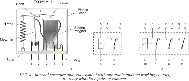
opened and closed using a magnet. Schematic of a relay is on 10.2. Copper
wire coil on ferrite core is used as a magnet. Above the magnet itself is
a plastic lever with iron head and a spring. In the middle of that lever
there is a metal fin with small platinum cylinders. Same cylinders are on
pins 1 and 2. When current is conducted through pins 4 and 5 to the coil,
lever is drawn to the magnet, which disconnects fin from pin 2, thus
opening the circuit between 3 and two. Fin is connected to the cylinder on
pin 1 and closes the circuit between pins 3 and 1. When there is no
voltage on 4 and 5, magnet is off and the lever springs back to it's
original position closing the circuit between pins 3 and 2 and opening one
between 3 and 1.

Simplest relay is displayed on 10.2a. There are far more
complicated relays in existence, where an electro magnet activates more
switches. On 10.2b is a relay with three pairs of switches.
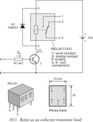
Relay is
usually connected as a collector load of a transistor, as shown on 10.3.
When the input voltage is high enough (between points A and B), so that
the base voltage (voltage between base and ground, or between base and
emitter, because its connected to ground as well) is higher than 0.7V,
current IB flows through base, and IC flows through the collector. This
current flows through the electro magnet's coil, this draws the lever with
the fin, and this breaks the connection between pins 2 and 3 and connects
pins 1 and 3.
Lower part of the 10.2 represents a shape and pin
placement of a relay.
Since relay is an electro mechanic component
which is consisted of moving parts, it has a limited operational life
span, and cannot be used for rapid switching. It would not be very
effective using it in a, for example, light show which has frequent
switching frequency (several hundreds or thousands times per hour). Each
opening and closing of the contact is followed by sparks which would
dramatically shorten the life of such device.
When choosing a relay,
two value numbers are most important to us:
-
electro magnet's coil, and
-
relay contacts to which is connected the controlled
device.
1. Coil values are “input values” or voltage and
resistance values at which relay draws the lever and switches. Usual
coil voltage values are 3V, 5V, 6V, 12V and 24V. They can be found
printed on the relay's housing. These are all DC voltages, but there
are AC voltage designed relays with 230V/250V. Depending on the
resistance of the coil is the current flow value. Usually resistance
is, with the voltage, marked on the housing of the component,
and if this is not the case, it can be easily measured. Current
flowing through the relay is calculated using Ohm's law, by dividing
relay's voltage with it's resistance. For example, relay we used was
12V, using the multimeter we measured it's resistance was 300Ohm,
which means that current flow through the coil is: with the voltage, marked on the housing of the component,
and if this is not the case, it can be easily measured. Current
flowing through the relay is calculated using Ohm's law, by dividing
relay's voltage with it's resistance. For example, relay we used was
12V, using the multimeter we measured it's resistance was 300Ohm,
which means that current flow through the coil is:
I=U/R=12/300=40mA.
2. Voltage on relay's contacts, also
marked on the housing, is a maximum value allowed, this value should
not be neglected, since disregarding it would cause intense sparks
inside of the relay itself and possibly serious damage to all devices
connected to it. If you want to switch some home appliance operating
off the mains grid, relay contact's maximum rating should be 250V
(this is, as with all other components, valid if mains is 220V in your
country, if you live in United States, you should use a relay intended
for 120V, this goes pretty much for Japan as well)
Maximum current rating relay's can sustain is marked on
the housing with all other info, usually above 1A, and commonly higher
than 10A.
Maximum power rating of a controlled device is calculated by
multiplying the maximum current rating with relay's pin voltage. If, for
example, maximum allowed current flow rating is 8A, and the voltage is
220V, highest allowable power rating is:
P=I.U=8.220=1760
W.
Transistor from picture 10.2 should have at least twice high the
value of voltage between collector and emitter than battery's voltage (24V
in our example), and that maximum collector current rating is higher than
current rating through the coil (this is 40mA in our example).
10.2
Examples
Modern telecommunication systems were born on May 24th
1844. On this day Samuel Morse established a transfer of telegraphic
signals between Washington and Baltimore. This transmission has been
conducted over a wire line. Half a century later, wireless, radio
transmission was introduced. Soon after that, transmission of sound, and
after that picture. Since the very beginnings, amateurs formed a strong
base around radio transmission. At first they established communication
using telegraphy, but soon equipment for audio communication was within
reach of amateurs. Nowadays most radio enthusiasts communicate over
satellite. Telegraphy is the most primitive form of radio communication,
but still has people interested in it.
Telegraphy amateurs use series
of abridged phrases, forming their own lingo, which speeds up the
communication. OK, for example stands for everything is alright, TNX –
thanks, QRS – drop the typing speed. One of them is QRP, or drop the
transmission power, is also used as a reference for low power CW
transmitters.
Schematic of an interesting 0.5W QRP transmitter is on
10.4. Central component of this transmitter is a logic gate 74HC240.
According to radio amateur's holy bible “The ARRL Handbook” 1998. edition,
American amateur Lew Smith, or N7KSB, successfully communicated to radio
amateurs in over 30 countries on every continent.
Chip 74HC240 has
eight inverting amplifiers, commonly used as buffer circuits in digital
electronics. One of the buffers, on 10.4, whose input is on pin 11 and
output on 9, connected to other components forms an oscillator. This
oscillator's frequency needs to be very stable, it must not change on
temperature or supply voltage variations, etc. This is achieved using a
quartz crystal oscillator labeled as Q on the schematic.
Signal from
the oscillator is amplified using the amplifiers made of four buffers
connected in parallel. Inputs of these buffers are on pins 2, 4, 6 and 8.
Unused buffers on 3, 5, and 7 are connected to ground and outputs remain
unconnected (acronym NC you can find on some schematic means Not
Connected). Amplified HF signal from the amplifier is on pins 12, 14, 16
and 18 and is connected to coils L1 and L2 and capacitors C7 and C8, to
the connector U. This filter represses higher harmonies of the HF signal
created by the oscillator. Signal from the oscillator produces square
voltage, rich in harmonics and these could interfere with other radio
devices, so that part of the circuit is highly recommended. Coaxial cable
with 50W impendance is plugged into the connector U. This cable leads HF
signal to the emitting antenna.
* Transmitter is supplied from 8V
DC voltage. Higher voltage should not be used, since this could lead to
overheating and damaging of the integrated circuit.
* Since this
circuit generates an excess heat, heatsink should be added to the design.
It could be bought as an “off the shelf” product or made out of an around
1mm thick aluminum sheet, which is glued to the circuit using an epoxy
resin or a special paste used to glue heatsinks to your CPU of the
PC.
* Coil data is given in the spreadsheet in the upper right
corner of the picture. They are wound using a 1.6mm copper wire with laque
insulation. As shown, you wind the coil using a 9.5mm drill bit. Make sure
you wind it tight, curl to curl. Then, you remove the coil from the drill
bit and stretch it, so that it's total length is as shown on the
spreadsheet.
* When pin 1 is connected to ground, oscillator
operates, this is achieved by pressing the momentary switch. Resistor R1
and capacitor C3 form a low pass filter. This circuit removes “clicks”
which appear when switch's contacts open or close.
* Quartz crystal
Q has the same resonant frequency as transmitter (30MHz, 20MHz or 15MHz).
To establish transmission, transmitter must “fall into” the antenna range
(28MHz, 21MHz or 14MHz) and this is achieved by tuning the trimmer
capacitor Ct.
On 10.5 is an example of a classic shielded cable
application. Received LF signal is routed to the amplifier circuit using
an ordinary microphone cable. Shielding, made of a conducting wire laced
into a net is connected to ground, and the wire core is connected to the
amplifier. In the same manner, using a double core shielded cable, a
potentiometer, used to regulate the volume is connected to the circuit.
Pictures 9.7 and 9.8 hold information applicable to this circuit as
well.
|

