Thyristors, triacs, diacs
There are several thyristors displayed on 6.1. Triacs look the same as
them, while diacs look like small power rectifying diodes. Their symbols,
used to represent these components on schematics, and pin positions for
some of them, could be found on 6.2.
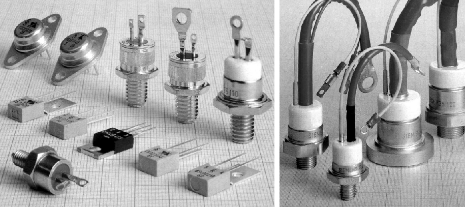
Fig.
6.1: Several thyristors and triacs
It should be said that thyristor is actually an improved strong diode.
Besides anode (A) and cathode (K) it has another lead which is commonly
described as a gate (G), as found on picture 6.2a. The same way a diode
does, a thyristor conducts current when the anode is positive compared to
the cathode, but only if the voltage on the gate is positive and high
enough as well. When thyristor starts conducting (from anode to cathode)
voltage on the gate is of no importance to us any longer, and thyristor
can be switched off only by breaking the circuit on the anode side. For
example, look at the picture 6.3. If the circuit was closed using switch
S1, thyristor would not conduct electricity, and so bulb won't light. If,
even for a very short time, switch S2 was closed, bulb would light. Only
by opening S1 will shut the bulb again. thyristors are marked in some
schematics as SCR, which is an acronym for Silicon Controlled
Rectifier.
Triac is very similar component to thyristor, with the
difference that it can conduct electricity in both directions. It has
three electrodes as well, called anode 1 (A1), anode 2 (A2), and gate (G).
It is used for regulation of alternating current circuits. Devices such as
hand drill speed controller or bulb light controller could be realized
using a triac, which we will discuss at a later point.
thyristors and
triacs are marked alphanumerically, KT430, for example. In schematics it
is common to find only their properties, like expected voltage and
current, and not exact product mark. In those cases any thyristor or
triac, satisfying given values, could be used.
Low power thyristors and
triacs are packed in same housings as transistors, but high power ones
have completely different shell. These are shown on the upper side, and on
the right of the picture 6.1. Pin placement of some more common thyristors
and triacs is shown on picture 6.2 a and b.
Diacs (6.2c), or two-way
diodes as often referred to, are used together with thyristors and triacs.
Their main property is that their resistance is very large until voltage
on their ends exceeds some predefined value. That pass-through voltage is
commonly 30V. So, while voltage is under 30V diac responds as any common
large resistance resistor, and when voltage rises over 30V it acts as a
low resistance resistor. Housing of a diac isn't different than packing of
the common low power rectifying diode.
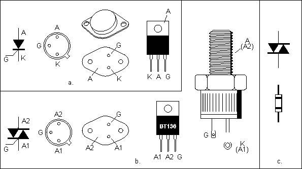
Fig.
6.2: Symbols and pin placements for: a - thyristor, b - triac, c -
diac
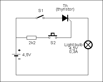
Fig.
6.3: Thyristor principle of work
1. Practical examples
Picture 6.4 displays a schematic of a simple household alarm
device using thyristor. Main switch, S1 enables and disables the device.
Switch S2 is supposed to open when alarming event occurs (break-in or fire
or something else, depending on the sensor used as S2). While this switch
is closed, base and emitter are short-circuited (and therefore UBE = 0)
and transistor is stopped from conducting electricity. Therefore there is
no current on the gate of the thyristor. When S2 opens, even for a very
short amount of time transistor starts conducting electricity and over it
the thyristor's gate receives positive voltage, which makes thyristor
conductive. This conducted current flows through a lightbulb, which turns
on. Closing S2 again will not stop thyristor, which means that fast
closing the opened door is not of much use to the burglar. Only switch
that could shut down the alarm is the S1. Instead of S2, any kind of
transformer which has low resistance in normal conditions so thyristor
would remain closed. When alerting state occurs it's resistance should
rise, which will end up in a lit bulb.
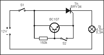
Fig.
6.4: Alarm device using a thyristor and a transistor
Picture 6.5 signals that light is lit in the room which shouldn't have
this occurring. While the light is out photo-transistor doesn't conduct
electricity. When light occurs transistor conducts current and alert is
risen. This means that thyristor conducted electricity to the electric
bell which begins to signal intrusion. Killing the light wouldn't stop the
alarm. Again, that would be possible only switching S1.
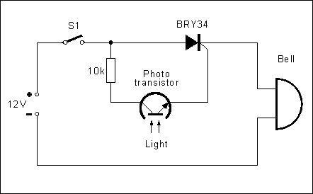
Fig.
6.5: Alarm device using a thyristor and a photo-transistor
Bulb-blinker is devised using diacs and triacs, and is represented by
the schematic on picture 6.6. This circuit, enables bulb (220V, 40W) to
toggle bulb several times per second. Mains voltage is regulated using the
1N4004 diode. Capacitor (220uF) is charged with the DC, so it's voltage
rises. When this voltage reaches passing value (30V) of the diac,
capacitor discharges over the diac and triac. This current impulse
switches the triac and that lits the bulb for a very short amount of time,
after some period of time (which could be custom set using the 100kOhm
potentiometer, capacitor is full again, and the whole cycle repeats.
Trimmer sets current level which is needed to trigger the triac.
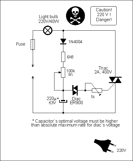
Fig.
6.6: Flasher
Light intensity or speed control for the collector motors used in power
tools, hair dryers or some kitchen appliances is displayed on schematic
6.7. Any of the mentioned devices could be encased in a box, where all
components for that circuit would reside. Mode of operation is the same as
the previous example. Electric filter which disables large electronic
interferences generated by the triac's operation to pass on and interfere
with the proper operation of the TV receiver and other devices, is based
on a coil (Lf) and a capacitor (Cf).
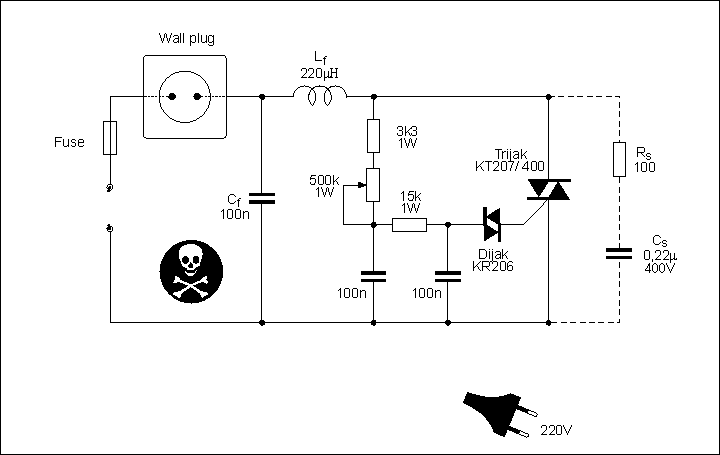
Fig.
6.7: Light bulb intensity or drill motor speed regulator
If sole usage for this device is to control the brightness of a light
bulb, then RS resistor and CS capacitor aren't
necessary.
|