Diodes
As with transistors, diodes are fabricated out of semiconducting
materials. So, the first letter in their mark could be an A (germanium
diode) or B (silicon diode). They can be encased inside of a glass, metal
or plastic housing. They have two leads: a cathode (K) and an anode (A).
The most important property of all diodes is that their resistance is very
small in one direction, 6O for example, and very large in the opposite,
i.e. 600 kO. What this means is that when a diode is in an electrical
circuit, voltage on the anode is higher than the voltage on the cathode,
and it acts like a low value resistor (6O). If it is connected in the
opposite direction it acts like a large value resistor (600 kO). In the
first case, it is referred to that diode as conducting polarized, and as
nonconducting polarized in the second case.
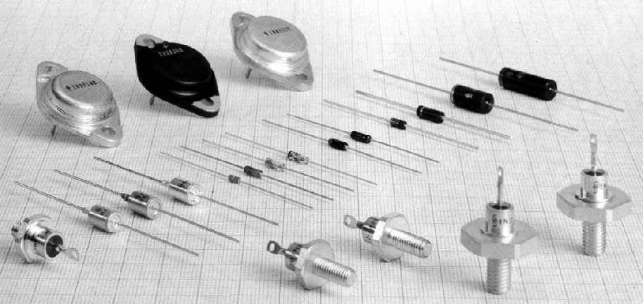
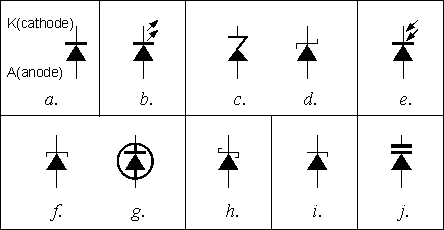
Picture 5.1 depict several
different diodes, and picture 5.2 shows their symbols.

Fig. 5.1: Several different types of
diodes
Transforming diodes are, as their name states, used in transformers,
whether as single components or as four diodes inside of a housing. They
are called Gretz (or bridge) rectifier.
On the other hand, there are
diodes whose primary characteristic of having passing and non-passing
direction is of no importance. They have other capabilities, and are used
in other circuits than transformers.
Symbol in 5.2a is standing for
regular transforming diode (some of them are 1N4001, BY238, AY260, etc.).
They are designed in such a way to withstand relatively high current in
conducting direction, and voltage in non conducting direction. These are
their main characteristics.
HF, or detector, diodes are represented on
schematics using the same symbol as in rectifying doides (5.2a), but in
reality these two types are very different. These diodes are used for very
low currents, in circuits like the modulated signal detector in radio
receivers, voltage limiters, etc. They are mainly made of germanium, so
their marks are usualy starting with a letter A, AA121, for example.
Second A is used to specify that this is a HF diode. Most common package
for them is a glass tube tinted in some dark color (black or gray) from
which are coming two wires.

Fig. 5.2: Diode symbols: a - regulating and HF diode, b - LED,
c, d - Zener, e - photo, f,g - tunnel, h - Schottky, i -
breakdown,
j - capacitative
LEDs (Light Emitting Diodes) are constructed in form of
small red, yellow, green (or more rarely blue or transparent) light bulbs,
and they are used as light indicators. When they are connected to a DC
circuit, their polarity should always be considered. Anode must go to the
point where voltage is higher. On the other hand if circuit operates on
AC, LED's polarity is not important. Whenever LED is used in a circuit,
there should be a protective resistor connected in series with it, because
LED burns out without it. Several kilo-ohm resistor should be used for
operating on voltages under 20V. If the light is too dim value of that
resistor should be lowered, if on the contrary, light is too bright value
of the resistor should be higher.
Zener diodes (5.2c and 5.2d) are
stabilizing diodes in transformers and they are used, as we applied, to
stabilize the voltage. Second letter in their mark is Z (BZ6, for
example). Number shows operating voltage of that diode. If there is an Y
behind the Z, that is high-power zener diode (BZY12, for example). Mark
could be formatted in some other way, but it always states the zener
voltage. There are diodes which are marked as ZPD5.6V or ZPY15V whose
operating voltages are 5.6V and 15V. Zener diodes are always non-pass
polarized, which means that DC voltage on the cathode is always positively
polarized comparing to the voltage on the anode.
Photo diode (5.2e)
is constructed in such a way that it allows light to fall on it's P-N
connection. When there is no light, Photo diode acts as a regular diode,
when current flows through it, it has high resistance in one, and low
resistance in opposite direction. When there is light both resistances are
low. In practice, this means that when there is no light voltage on the
anode is lower than the voltage on the cathode so diode is polarized
negatively and acts as a large resistance resistor. But when the light is
on, it's resistance is lowered which makes this diode appropriate for
different alarm and signal devices. Photo diode and a LED are main parts
of optocouplers (who will be discussed in more detail in chapter
9).
Tunnel diode (5.2f and 5.2g) is commonly used in oscillators
with very high frequencies. It is conducting polarized in operating
conditions. When DC voltage is set to a needed value, diode, for AC
current, acts like a negative resistance resistor.
Schottky diode
(5.2h) is used on extremely high frequency rates as well as with high
power transforming devices (because of it's low voltage drop in pass
direction) on frequencies of 100kHz order.
Breakdown diode (5.2i)
is actually a Zener diode used in various different devices for protection
and voltage regulation. It passes current only when voltage rises above
some diode's predefined value. European standard symbol is on 5.2c, and
symbols on 5.2d and 5.2g are american standard symbolic representations of
this diode.
Varicap diode (5.2j) is used instead of a variable
capacitor in high frequency devices. It's polarized using a DC voltage not
to conduct current (cathode has higher voltage than anode). When this
voltage's value is changed, capacitance between cathode and anode is
changed. This diode is commonly used in radio receivers, transceivers,
oscillators, eg. every place that has a demand for variable capacitor with
relatively narrow range between it's minimum and maximum value.
Low
power diode's cathode is marked with a ring painted on the housing of the
component, but it is worth noting that some manufacturers label anode this
way, so it is best to test it with a multimeter (you'll commonly buy more
than one diode, and they come in strips, so it is only needed to test one,
others will be the same as that one).
Powerful diodes are marked
with a symbol engraved on the housing. If diode's internals reside in a
metal package, cathode is (not always) connected to it, and anode is a
lead that goes through a plastic cap in the housing.
5.1
Diode marks
European diodes are marked using two or three letters and a number.
Possible variation of this is a letter behind the number. First letter is
used to note the material used in manufacturing of the component (A -
germanium, B - silicon), or, in case of letter Z, a Zener diode. The
second and third letter specify the sort and usage of that diode. Some of
the possibilities are:
A - a very low power diode, like the AA111,
AA113, AA121, etc. - they are used in the detector unit of a radio
receiver; BA124, BA125 : varicap diodes used instead of variable resistors
in different receiving devices, oscillators, etc., BAY80, BAY93, etc. -
switching diodes used in devices which operate using logic circuits.
BA157, BA158, etc. - these are switching diodes with short relapse
time.
B - two capacitive (varicap) diodes in the same housing, like
BB104, BB105, etc.
Y - regulation diodes, like BY240, BY243, BY244,
etc. - these regulation diodes come in a plastic packaging , and operate
on maximum current of 0.8A. If there is another Y behind this one, diodes
specifics remain the same, except that they are intended for higher
currents. For example, BYY44 is a diode whose absolute maximum current
rating is 1A. When Y is the second letter in a Zener diode mark (ZY10,
ZY30, etc.) that means that it is intended for higher power usage.
G,
G, PD - different tolerance marks for Zener diodes. Some of these are ZF12
(5% tolerance), ZG18 (10% tolerance), ZPD9.1 (5% tolerance).
Third
letter is used to specify the branch of certain two-letters model type
with some specific property (designed for higher currents, for
example).
American markings are beginning with 1N followed by a number,
1N4001, for example (regulating diode), 1N4449 (switching diode),
etc.
Japanese style is similar to american, the main difference is in
that instead of N there is S, 1S241 being one of them.
Russian diode
marks are consisted of two numbers (GD - germanium, KD - silicon) and a
number.
As with transistors, number does not have some deeper meaning,
it is there only to help users find that specific model in a catalog and
see it's specifications. Only difference to that, as already mentioned,
are Zener diodes, whose number shows operating voltage of the certain
Zener diode.
5.2
Diode characteristics
The most important characteristics when using power diodes used in
transformers and similar devices are maximum current rating in conductive
direction (IFmax), and maximum voltage they could withstand in
non-conductive direction(URmax).
One should bear in mind that
characteristics read on schematics are effective values. Maximum values,
which are important for selection of certain diode are calculated when
their effective value is multiplied by 1.41. For example, if the schematic
of certain transformer states that secondary voltage of some transformer
connected to the wall plug is 12V, maximum voltage of this voltage is 17V,
so the diode should have URmax>17V.
Important characteristics
for Zener diodes are Zener voltage (UZ) and Zener current (IZ) and maximum
dissipation power (PD).
When working with capacitative diodes it is
important to know their minimal and maximal capacitance, as well as values
of DC voltage during which these capacitances occur.
With LEDs it
is important to know the value of current nd voltage which pass through
the diode when the light of the component is brightest. Voltage comes from
1.6V to several volts., and current goes from several mA to several tens
of mA. It is a common thing to connect a protective resistor in series
with a LED, whose values is easily acquired through
experiment.
Beside universal transistors TUN and TUP (mentioned in
Chapter 4.4), there are universal diodes as well. They are marked with DUS
(for universal silicon diode) and DUG (for germanium one). These diodes
have following characteristics:
5.3 Practical examples
The schematic of a stabilized transformer (3.8) has several diodes. The
first four of them are in a single package with mark B40C1500. This is the
well known Gretz (or bridge) rectifier which is a two way rectifier for
24V AC.
LED is used to optically indicate that transformer is working.
The resistor R1 is used to protect the diode, diode's brightness is
changed with the change of it's value.
Diodes marked as 1N4002 are
protecting integrated the circuit if a consuming device (which is
connected between points + and -) has a large electrolythic
capacitor.
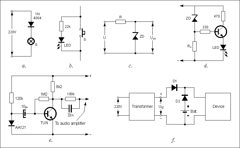
There are several other examples of the usage of diodes on
picture 5.3. Light bulb's lifespan could be prolonged using the device on
5.3a. By simply connecting a diode to a light bulb in series current
passing through a bulb is halved and it last a lot longer. Of course,
there is a downside to this method: brightness of the bulb is lowered and
the light becomes yellow, so this solution s optimal for use in building
corridors and other places where there is a need to have a long lasting
light source but don't need it to be very bright. Diode should have an
inverse voltage of over 400V, and a current higher than the light bulb's.
Some of them (for a 200W bulb) are 1N4004 and a BY244.
While we are
discussing building corridor lights, 5.3b shows a way to connect a LED to
the switch, so that it lights only when the light bulb is off for easier
finding in the dark. Both the resistor and diode are placed in a switch
housing, with LED peeking through a hole on the switch. (Of course, this
is commercially available for a long time, so this is only to show how are
those circuits which you'd normally buy function)
Very simple DC
voltage stabilizer for low currents could be made using the schematic 5.3d
as a reference.

Fig. 5.3: a - using a diode to prolong the light bulb's
life span, b - stairlight LED indicator, c - voltage
stabilizer,
d - voltage rise indicator, e - backup supply, d - rain
noise synthetizer
Unstabilized voltage is marked with an U, and stabilized with UST.
Voltage over the Zener diode is equal to UST, so if we wanted to achieve
stabilized 9V, we would have used ZPD9.1 diode. Although this stabilizer
has limited usage it is the base design found in all power supplies
today.
We could also devise a voltage overload detector, 5.3d has a LED
connected to the circuit as a signal that voltage is over some predefined
value. While voltage is lower than the operating voltage of the Zener,
diode acts as a high value resistor, so DC voltage on the base of the
transistor is very low, which means it is not conducting electricity. When
the voltage rises to equal the Zener voltage, it's resistance is lowered,
and transistor receives enough electricity on it's base to start
conducting electricity, which lights the LED. This example has 6V Zener
diode, which means that LED is lit when voltage reaches that value. For
other voltage values, appropriate Zener diode should be used. Brightness
and the exact moment of lighting the LED could be set with the right value
of Rx resistor (in several kO range).
To modify this circuit in the way
that it signals voltage drop below some predefined level, all one should
do is swap places of the Zener diode and Rx resistor. For example, by
using 12V Zener diode in this manner, we could make an car battery level
indicator. So, when voltage drops below 12V, battery taken out from the
car and recharged.
A bit odd usage for a diode is shown on 5.3e. It is
the noise synthesizer, which produces rain like sound. DC current flowing
through the conducting polarized diode AA121 isn't absolutely constant,
but changes over some middle value (which would be shown using ampermeter
connected in series with the diode). This variable component which creates
the noise is amplified using transistor (any NPN transistor) and passed
over a filter (resistor-capacitor circuit vuth values 33nF and 100kOhms)
is brought to an audio amplifier and reproduced on a speaker.
One day,
author of this book ran really late to work, which by the way cause
enormous amount of joy among his students for loosing first three classes.
This all happened because of the power failure in the electrical grid,
which led to his electrical alarm clock reset (this is the
other-side-of-the-fence equivalent to the "dog ate my homework"). In these
situations, when some critical device looses it's main power supply,
back-up power from the battery should come into picture and remain normal
functionality of said device. Schematic 5.3f shows how two diodes, which
are able to operate on voltages needed by the device, and a battery are
added to the stabilized transformer (this can be any off the shelf
transformer you already have for your home appliances). For this to
function properly, UIZ voltage should be a bit higher than the voltage
over the battery. That makes D2 diode nonconducting, so battery doesn't
supply. When network voltage drops, UIZ is zero so D2 conducts
electricity, and battery supplies needed electricity.
D1 is there to
prevent battery to power the transformer, which is needed to prolong the
battery life, and protect transformer from damage. For devices up to 1A
diode 1N4001 is sufficient, and 1N5400 if amperage is up to 3A |

